previous | start | next

RS232 Interface

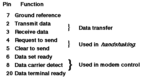
This interface was originally based on a 25 pin connector[1]. In the following, signal names refer to the computer (or DTE) end of the link: for example, pin 2 is "Receive data" on a modem -- that is, an RS232 cable is wired "straight-through". Major signals defined in RS232 are:
RS232 pin definitions
The RS232 interface was designed to connect a modem (DCE) to a computer (DTE). To make a direct (DTE-DTE) link, a null modem cable (or null modem adapter) must normally be used. This is sometimes called a crossover cable, since pin 2 at one end is wired to pin 3 at the other, etc.
 
More modern alternatives to the ubiquitous RS232 interface include USB and firewire, although most modern systems use a built-in modem.
 
[1] 9 pin connectors are also used, but there is no standard pin assignment for this -- the PC/AT pinout is the most common.
Lecture 14: Point-to-Point Data Links Copyright © 2002 P.Scott, La Trobe University Bendigo.


previous | start | next